|
 |
|
Xtenna
Antenna & Tags
Reader |
| Xtenna |
| Q. |
What is an Xtenna ? |
| A. |
Xtenna is an integrated RFID Antenna/Reader in a single housing, using Power on Ethernet technology, thus alleviating scarce multiple wall power source. |
| Q. |
What is Power on Ethernet and how does it help Xtenna ? |
| A. |
It is the use of Ethernet cable to transfer power on the same cable as TCP/IP signal , separated at destination using a Mag Jack and thus able to power a remote device, within reasonable power requirements. Xtenna deploys this technology to power 24 Xtennas from a single Power on Ethernet Switch, remotely. Thus there is a single wall power source for the 24 port switch which powers Xtennas upto 330’ away. This could be helpful in areas where power may not be available easily. |
| Q. |
What advantage does Xtenna have over ordinary Antenna / Reader ? |
| A. |
Xtennas are connected using inexpensive CAT 6 cable which carries Digital signal. This alleviates 4 major issues :
a. Multiple wall power source ( each Reader within 25’ distance of Antenna will need a wall power source Vs.
Xtenna having a single power source for the switch and driving upto 24 Xtennas at a distance of 330’) ,
b. Distance limitation ( Digital cable length of 330’ Vs. 25’ of RF cable ) ,
c. High cost ( inexpensive CAT 6 Vs. expensive RF cable ) and
d. Signal integrity ( Digital Vs. RF analog signal ). |
| Q. |
Why has Xtenna design been based on Dual circular polarization ? |
| A. |
Dual circular polarization is actually two antennas under the same radome with two interfaces for Transmit and Receive. Essen has chosen inversed polarization - the transmit signal having RH polarization and receive signal having LH polarization, thus generating less inetrference between both signals. Also an antenna’s radiation pattern is based on Fourier Transform ; thus larger Antennas have narrow main beams & side lobes, which are better. |
| Q. |
Does Power on Ethernet have any standards ? |
| A. |
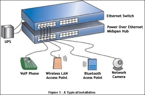
PoE has just become an international standard, called IEEE802.3af, as an extension to the existing Ethernet standards. The freezing of the standard will allow an explosion of Power Over Ethernet devices and installations. Power Over Ethernet is likely to be ubiquitous in a few years, as the cost of adding the power supplies to the Ethernet switches is going to be small. Indeed, it offers the first truely international standard for power distribution.
Figure 1 shows a typical system. In the wiring cabinet existing Ethernet switch equipment is retained and a "midspan" power source injects power into the twisted pair LAN cables. At the other end of the cables the power is used to run phones, wireless access points, cameras and other appliances. An Uninterruptable Power Supply (UPS) can optionally support the installation in the case of power failures.
|
| Q. |
Why is Power on Ethernet used ? |
| A. |
Here are some reasons:
- Only one set of wires to bring to Xtenna - simplifies installation and saves space.
- There is no need to pay for an expensive electrician, or delay your installation to meet the electrician's schedule - saves time and money.
- Xtenna can be easily moved, to wherever you can lay a LAN cable - minimal disruption to the workplace.
- Safer - no mains voltages anywhere.
- A UPS can guarantee power to the appliance even during mains power failure.
- As well as the data transfer to and from the appliance, you can use SNMP network management infrastructure to monitor and control the appliances.
- Xtenna can be shut down or reset remotely - no need for a reset button or power switch.
- In wireless LAN systems it simplifies the RF survey task, as the access point can easily be moved and wired in.
- A standard CAT 6 Ethernet cable has four twisted pairs, but only two of these are used for 10BASE-T and 100BASE-T.
- The spare pairs are used. Pins 4 and 5 connected together and forming the positive supply, and the pair on pins 7 and 8 connected and forming the negative supply. (In fact, a late change to the spec allows either polarity to be used).
- The data pairs are used. Since Ethernet pairs are transformer coupled at each end, it is possible to apply DC power to the center tap of the isolation transformer without upsetting the data transfer. In this mode of operation the pair on pins 3 and 6 and the pair on pins 1 and 2 can be of either polarity.
|
|
|
| Antenna & Tags |
| Q. |
How many types of UHF antennas are there ? |
| A. |
There are various types available , the most popular being, Linear, Monostatic Circular, Bistatic Circular. Linear antennas have best wave propagation when the tag orientation is known and fixed. The tag and antenna have to be matched in polarization. Circular polarized antennas are used when the tag orientation is unknown. The mono-static antenna has a single lobe. It transmits and receives signals through a common port. The bi-static antenna is actually two antennas under the same radome with two ports.The transmit signal is beamed through one lobe and the receive signal with the other lobe. |
| Q. |
How is antenna gain ascertained ? |
| A. |
The antenna gain is directly proportional to the size of the lobe.If antennas has the Azimuth beam different in size from Elevation beam, the wider side controls the narrower beam. |
| Q. |
What are Passive UHF Tags ? |
| A. |
Passive UHF tags have no internal power supply. The minute electrical current induced in the antenna by the incoming radio frequency signal provides just enough power for the IC in the tag to power up and transmit a response. Most passive tags signal by backscattering the carrier wave from the reader. This means that the antenna has to be designed both to collect power from the incoming signal and also to transmit the outbound backscatter signal. The response of a passive RFID tag is not necessarily just an ID number; the tag chip can contain non-volatile, possibly writable EEPROM for storing data.
Passive tags have practical read distances ranging from about 10 cm (4 in.) up to a few meters (EPC) and (ISO 18000-6 ), depending on the chosen radio frequency and antenna design/size. Due to their simplicity in design they are also suitable for manufacture with a printing process for the antennas. The lack of an onboard power supply means that the device can be quite small: commercially available products exist that can be embedded in a sticker, or under the skin in the case of low frequency RFID tags. |
| Q. |
How are UHF Tags made ? |
| A. |
UHF tag antennas are usually fabricated from copper or aluminum. Conductive inks have seen some use in tag antennas but have encountered problems with IC adhesion and environmental stability. |
| Q. |
How are Tags attached ? |
| A. |
There are three different kinds of RFID tags based on their attachment with identified objects, i.e. attachable, implantable and insertion tags. |
| Q. |
How are Tags positioned ? |
| A. |
RFID tagging positions can influence the performance of air interface UHF RFID passive tags and related to the position where RFID tags are embedded, attached, injected. In many cases, optimum power from RFID reader is not required to operate passive tags. However, in cases where the Effective Radiated Power (ERP) level and distance between reader and tags are fixed, such as in manufacturing setting, it is important to know the location in a tagged object where a passive tag can operate optimally. R-Spot or Resonance Spot, L-Spot or Live Spot and D-Spot or Dead Spot are defined to specify the location of RFID tags in a tagged object, where the tags can still receive power from a reader within specified ERP level and distance |
|
|
| Reader |
| Q. |
How do Readers , read Tag data ? |
| A. |
In order to read tag data, readers use a tree-walking singulation algorithm, resolving possible collisions and processing responses one by one. Blocker Tags may be used to prevent readers from accessing tags within an area without killing surrounding tags by means of suicide commands. These tags masquerade as valid tags but have some special properties: in particular, they may possess any identification code, and may deterministically respond to all reader queries, thus rendering them useless and securing the environment. |
|
|
|
|
|
|